Products
 

---Lesson 2--- 
CREATION TECHNIQUES

arrow down
  • Keyboard Commands and Macro Keys
To become highly proficient as a CADVANCE designer, it is essential that you utilize the keyboard commands. As you familiarize yourself to the CADVANCE command structure, you should expect to use the mouse frequently. However, you should be practicing with this sheet in front of you to serve as a reminder until you've mastered the keyboard commands.

Use of these keys will provide you with both speed and accuracy in your designs.       

Numbers on the left are a good indicator of most frequently used keyboard commands in CADVANCE.  Double asterisks (**) indicate that same function can be utilized in most Windows programs.

**      F1

Displays CADVANCE Help Screen

#4     F2  Edit / Move
#7     Ctrl + F2 Offset a point
Shift + F2 Edit / Duplicate / Single
F3                           Options / Select - sets the cursor trap distance
F4                            Toggles working plane trap distance in 3D
**      Alt + F4 File / Exit
Shift + F4 File / Close
#5      F5      Redraw - refreshes the current screen
#6      F6   Repeat the last command
F7                          Changes the X and Y step sizes when utilizing the arrow keys to move
F8                          Options / Cursor - allows you toggle through the 3 cursor types
F9                          Utility / Macro / Run
Shift + F9 [key]  Same as F11 (too many key strokes...use F11)
**      F10 Toggles cursor between main menu and drawing ( see Alt [key] below)
F11 + [key]  Run a macro you've assigned to a specific key
**      F12   File / Save As
**      Ctrl + F12 File / Open
 **     Shift + F12 File / Save
Ctrl + Shift + F12  Prints the active drawing
Shift + Click Adds to a group of currently selected objects
Ctrl + Click  Subtracts from a group of currently selected objects
**#8   Ctrl + Z Edit / Undo to the Clipboard - be careful! (Also Alt + Backspace)
**      Ctrl + X  Edit / Cut to the Clipboard (also Shift + Del)
**      Ctrl + C Edit / Copy to the Clipboard (also Shift + Insert)
**      Ctrl + V  Edit / Paste from the Clipboard (also Shift + Insert)
**#3   Del  Edit / Delete highlighted object
Spacebar                 Same as clicking left mouse button to select
Esc                         Same as clicking right mouse button to Alt command
**       Alt Toggles the cursor between the main menu and the drawing, enter the underlined menu letters as command shortcuts (same as F10 or / - front slash)
#1      . (period)  Sets the Snap Mode, allowing you to enter underlined snap commands
[       (open bracket)  Sets the Coordinate Display Mode (ABS, REL, POL, PAB)
#2      ] (close bracket) Allows coordinate input
O Changes object selection method
S Displays the Setup dialog window


  •  Drafting Accurately - The SNAP Commands

Drafting with a computer isn't really much different than drawing by hand, but you must master the various locking or snap commands on a computer to create accurate designs. These commands are used instead of rulers or the blue lines you find on drafting paper and they assist you in placing elements exactly where they should be. If your drawings are created with precision, then all future reference made from them will be accurate. It is essential that you utilize and master the SNAP commands.

The SNAP commands can be easily accessed by using the period (.) key on the keyboard.


  • Grid

The CADVANCE GRID command allows you to create a grid dot matrix on the screen. When you are in Grid Lock, you will note that the cursor always SNAPs onto these grid points and no others.


  • Node

A Node is merely a reference point that can be placed using the DRAW/NODE command and quickly snapped to at a later time using the Node SNAP (.N). Nodes will not plot and also disappear if you zoom or pan or redraw. The VIEW\VERTEX command is utilized to make them reappear on-screen. The most common use of nodes is in the symbol creation of doors, windows and line texture symbol elements. In these symbols, nodes create a break/snap point (this will be reviewed in symbol creation exercises).


  • Vertex

Every element in your drawing has one or more vertices which define how it was created. The Vertex Lock feature allows you to quickly "Snap" to these points and ensures design accuracy. Remember, all line endpoints are vertex points.


Lines                             Circles                              Arcs                                    Rectangles                    Nodes
2 Vertices                       1 Vertex                          2 Vertices                             4 Vertices                    1 Vertex  


  • The Other SNAP Commands
The remainder of the Lock Commands are pretty much self-explanatory. They include snapping to the nearest LINE (.L) or an INTERSECTION (.I) of two entities (like circles and rectangles). MIDPOINT (.M) snaps to the point on a line that lies midpoint between the two nearest vertices.  You can SNAP to the outer edge of a CIRCLE (.R) or even SNAP to the CENTER (.C) of a circle by selecting the outer edge of the circle. Where circles and arcs are concerned, you can also SNAP to locations on them set by the PIE ANGLE (.P) default setting (definition set under OPTIONS/MISCELLANEOUS). You can SNAP to the nearest point on an ARC (.A) as well as the ultimate generic, nearest OBJECT (.B) (which is anything). Finally, you can turn the Lock snap OFF (.O).

THE LOCK COMMANDS ARE VERY IMPORTANT AND SHOULD BE USED REGULARLY FOR ACCURACY!


  • Dimensioning
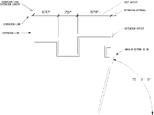
The Draw/Dimension/Setup dialog window is where the defaults are arranged prior to actual dimensioning. These settings are determined by plot scale, which specifies things like extension lengths and symbol and text sizes, and can be saved in a .DIM file. Most companies save a CAD.DIM as the most commonly used default (say 1/16" plot scale). They FILE/OPEN a variety of other .DIM's that easily reflect different scales ( such as 8.DIM for 1/8", 4.DIM for 1/4" and 2.DIM for 1/2"). We recommend that you always do like dimensions (i.e. all the horizontals, then all the verticals) at the same time.

Remember to utilize the S (Setup) key when dimensioning to quickly change the various "most used" dimensioning parameters.

The following diagram shows the locations of the hard-to-remember fields in the Dimension/Setup window:

(Click on picture for larger view)

Please remember that the HELP screens give you graphic details and reference to the various ways you can dimension in CADVANCE. Use them!


End of Lesson 2 - Next Lesson >>>

Home | Products | News | Technical | Forum | Gallery | Downloads | Links | About FIT